What is a Voltmeter? | How to use a voltmeter?
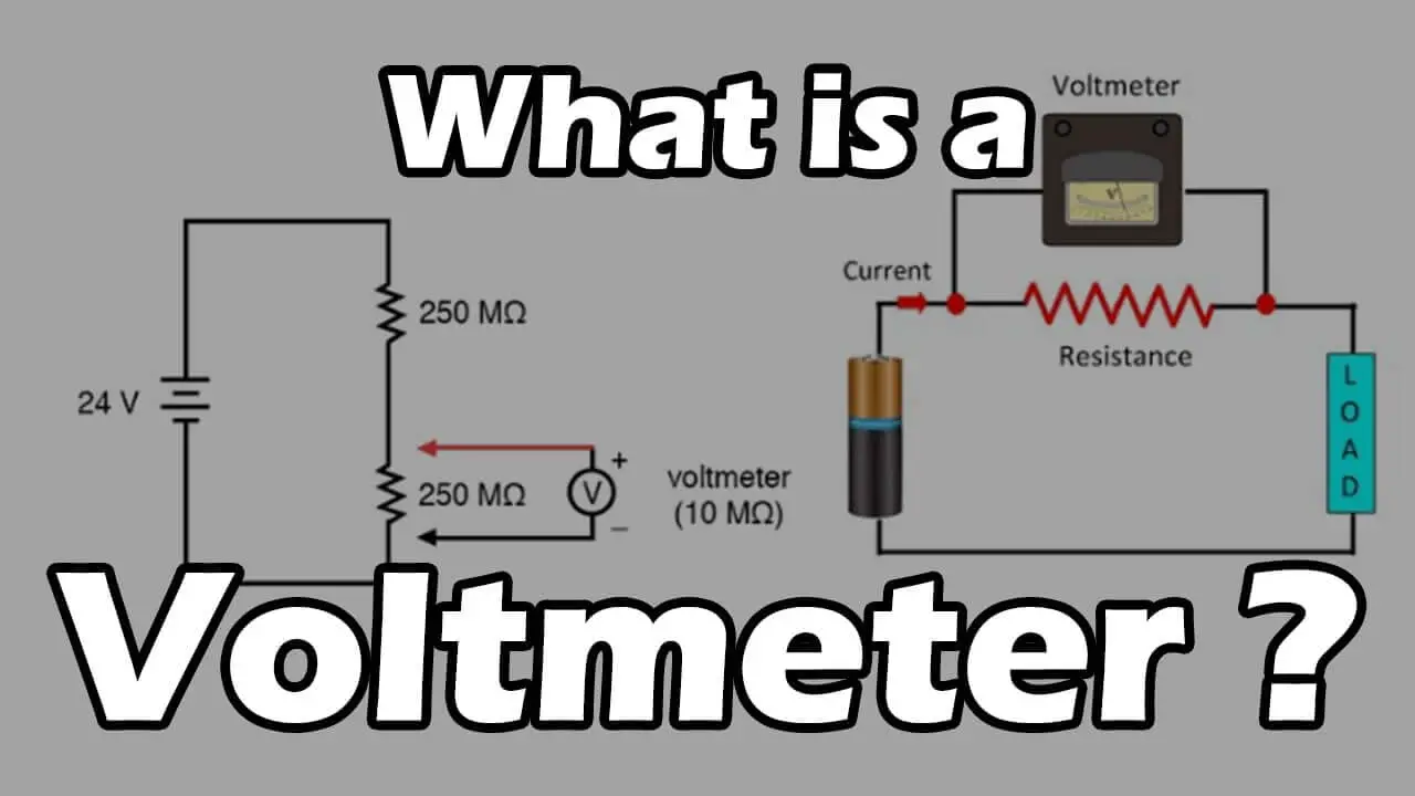
A voltmeter is a metering device used to measure electrical potential differences between two points in an electric circuit; The analog voltmeters move a pointer across a scale in proportion to the circuit’s voltage. In contrast, a digital voltmeter gives results in numerics.
Digital voltmeters give a numeric display of voltage using an analog to digital converter symbolic representation; a voltmeter is connected in a circuit, and in diagrams, it is represented by the letter V in a circle. Voltmeter working principle; the main principle of the voltmeters is that; Voltmeter is connected to a circuit in parallel in which we want to measure the voltage. The parallel connection is used because the voltmeter is constructed so that it has a very high value of resistance. A voltmeter is working on the principle of Ohm’s law; “the voltage across a resistance is directly proportional to the current passing through it”.

Classification or Types of Voltmeter
- Permanent Magnet Moving Coil (PMMC) Voltmeter
- Moving Iron (MI) Voltmeter
- Electro Dynamometer type Voltmeter
- Rectifier Type Voltmeter
- Induction Type Voltmeter
- Electrostatic Type Voltmeter
- Digital Voltmeter (DVM)
Depending on this type of measurement we do, we have:
- DC Voltmeter
- AC Voltmeter
How to use a voltmeter?
An analog multimeter is commonly just referred to as a voltmeter. It’s a very inexpensive tool to keep around your house. Analog meters are essential for a couple of applications around your home where you could use one to diagnose a few problems may have to use your voltmeter.
It has a set of included wires or leads to go with it. The black wire connects to the negative side of the terminals, and the red wire connects to the positive side of the terminals, and they are labelled. So just thinking about a car battery right is always positive on a car battery. This voltmeter will do a lot more than show you here today but keep things simple.
We use Voltmeter to test, DC Voltage Ohms, Resistance, AC Voltage
We are going to tell you D/C voltage Ohms or resistance and A/C voltage. The purpose of the Ohms or resistance meter is to determine whether or not there is a closed path or circuit for electricity to flow through.
We have to take two leads and push them together, and the meter goes to zero. There is zero resistance and a closed path for electricity to flow through. You can take that basic knowledge and use it to diagnose many different circuits in your house; simple circuits such as; an extension cord you can verify from one end of the extension cord to the other end with zero, on the scale. Make a full path, a closed path from one end to the other, and this particular wire is not faulty and works just fine. Let us take an extension cord, and every time you plug it into the wall to use it, it trips the breaker immediately, and you’re trying to figure out what exactly is going on.
If you take one end of the extension cord, and you start testing different combinations. You might be able to find–one or two particular wires are shorted out somewhere along the path. Two wires have shorted out, and that means this extension cord is no longer suitable or needs the same concept to test all kinds of stuff around your house.
Another example, a light bulb, if we connect one side over this bulb and then the other side of the lead at the bottom of the meter, to make a continuous circuit, that tells me, there is a continuous path through the lightbulb meaning. This lightbulb is good now let’s change from ohms to D/C voltage. An excellent example of where D/C voltage is used is in the batteries, now both the D/C voltage and the A/C voltage have different volt settings. Different maximum voltage settings and maximum number, you don’t want to exceed this so if we are using an 18-volts battery we don’t want to go down to 10 because I’m exceeding the voltage on this particular meter and it could cause harm to the voltmeter.
You always want to go to the next highest setting, so the next highest from 10 is 50 which is where I’ll test this 18-volt battery on D/C voltage settings. The red wire is connected to the positive and then the black wire is connected to the negative. You must connect these in the same series on your battery and as you can see here this is an 18 volts battery and that reads 18 volts.
Now, this could get a little confusing with all the different numbers in here but the way that this works is if I’ve set it to D/C 50 volts, maximum then according to this voltmeter the black lines in the middle two black numbers represent both A/C and D/C voltage. So I would go to the maximum number which is 50 that means the interior line or (the interior arc) is where my reading will take place. Therefore again, if we put it on the battery that interior middle line is two notches, shy of 20 which means that this 18-volt battery is reading at 18 volts, to go from testing D/C voltage batteries to the circuits in our house.
We need to go to A/C voltage now, typically the two circuits that we have are commonly referred to as 110 and 220-volts circuits, but technically speaking it’s a 120-volt circuit and, a 240-volt circuit, so go to the next highest number is 250 on this A/C voltage scale is a common 120-volt receptacle, and you can test it by putting the leads right into these slots of the receptacle, and the meter will show 120 volts of electricity this is a good way to show you. If this particular outlet is powered or not. Let us say you are working inside one of these electrical boxes and there is a set of exposed wires, and before you work with those wires, you need to verify that there is no electricity going to them. So you don’t be electrocuted the way you test exposed wires.
We are using these wires, for example again is with your A/C set to the correct voltage setting attached one of your leads to the white wire and the other lead to the black wire and if you are not getting any voltage on your reading then, that tells you that this particular set of wires has no voltage going to the circuit, and it is safe for you to work with these wires as needed. So what we have told you today; is just barely scratching the surface at how incredibly useful one of these tools can be.
There are a lot of problems, that you can diagnose around your house with one of these very inexpensive analog multimeters or a voltmeter, these multimeters are incredibly useful.
Let’s say you have a circuit here and you had a battery with a voltage v and there were resistors one, resistor two, and resistoR 3 up here, and there was current flowing through here. What if you wanted to experimentally measure the voltage across some of these elements?
You’d have to use a voltmeter. Voltmeter looks like this is a V, which is the symbol we use for a voltmeter.
How to use a Voltmeter by illustrating it in a diagram?
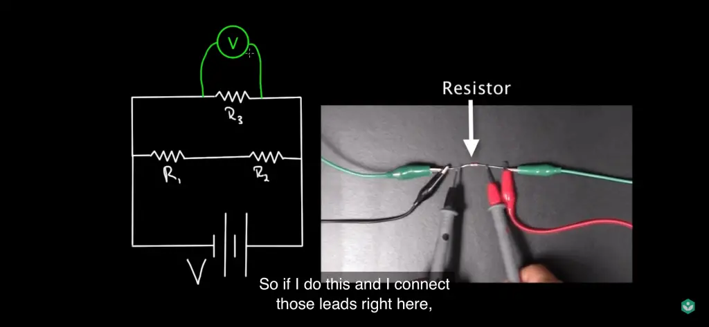
You take that voltmeter. I can’t plug it in the circuit like that. What I do is I take the leads of the voltmeter and I just connect them to either side of the circuit element that I want to determine the voltage across. So if I do this and I connect those leads right here, this voltmeter will tell me the voltage across (R 3). Or take the voltmeter, put it over here, and if I connect the leads across (R one) in parallel, notice I am hooking up the voltmeter in parallel. Voltmeters you always hook up in parallel. This now will tell me the voltage across R on and if I wanted to make sure my battery was functioning correctly, I could take my voltmeter and I can hook up the leads across the positive and negative terminals of the battery and see if the voltage across the battery is what I think it is. That’s how you use a voltmeter: always hooked up in parallel.
Why Do We Use an Ammeter?
But if we wanted to measure the current, we don’t use a voltmeter, we use an ammeter. And for an ammeter, you do not hook up an ammeter in parallel with the element you’re trying to measure. You will probably blow out the ammeter. I’ve done it a few times.
Don’t hook up the ammeter in parallel, why? But what you have to do is hook it up in series. So if we wanted to know the current going through (R), we could just stick the ammeter right in here. One lead would plug into one side of the ammeter, the other lead would plug into the other side. This current would have to flow straight and this is telling me how much current goes
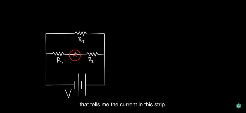
through (R 3). It doesn’t matter what side I put it on, the current going into (R 3) will equal the current going out. So you can put it over here too, but it has to be hooked up in series.
So you have to disconnect, it’s kind of a pain to hook up an ammeter sometimes. You have to disconnect something here, then connect that connection to the one side of the ammeter, connect to the other side of the ammeter. For a voltmeter, you didn’t have to do that. For a voltmeter, just keep it out and just touch those leads wherever you need to touch them. But for an ammeter, you have to break the circuit to let this ammeter in. But I can move it wherever I want. I could put it down here, that tells me the current in this strip. Again, ammeters are always hooked up in series with the element that you’re trying to measure. So this ammeter position will let me measure the current that’s flowing through the battery.
Why is the voltmeter always hooked up in parallel and the ammeter always hooked up in series?
We want the ammeter to be hooked up in series because we want to measure the current through a line in the circuit. We want to measure the current flowing through this resistor.
So if we want to measure the current flowing through something, we need to make sure that the current flows through our ammeter and that’s how we get our reading. Because of this, people design ammeters with very little resistance. An ammeter has very little resistance. And the reason is, if you took this ammeter and it had a big resistance and you stuck it in here, you’d be changing how much current flowed through this part of the circuit. We don’t want to do that. Whenever we measure something, we don’t want to disturb it.
So when we stick our ammeter, we don’t want to disturb how much current was going through here. We wanted to know how much current flows without my ammeter being in there.
So when I put my ammeter in parallel R3, it better has very little effect on this circuit.
That’s why we make this ammeter have very small resistance. And that’s also why you can’t hook this ammeter up in parallel, cause if you did, look at what would happen.
This is why it’s bad. If I took this ammeter and I hooked it upright and I hooked the other side up the left, look what the current’s going to do. I have got current flowing through here, current comes this way, goes this way, reaches this fork in the road and it’s got a choice.
It can go to the left or flow up through here and go through (R3) or flow through my ammeter. But the ammeter has very little resistance, meaning small, maybe on the order of a milliohm.
So all of this current that’s flowing through here, all this current’s going to choose to go through my ammeter. It is going to just skip all those resistors, forget that. it just goes through the ammeter.
If you’ve got a normal-sized voltage, maybe nine volts, three volts, hooked up to a milliohm, you’re gonna burn out your ammeter. There’s usually a fuse in here because they know people are gonna hook it up wrong. I’ve done that, and you burn out a fuse, you have to replace the fuse and it’s a pain. So don’t hook up your ammeter in parallel.
Why do we hook Voltmeters in parallel?
Well, a voltmeter is hooked up in parallel because we want to know the voltage across a circuit element, so on either side. Voltage is defined to be the difference between electric potential at two points in space. It makes no sense to ask what’s the voltage through a certain point in a circuit. You can ask what current flows through that point in the circuit.
But asking what the voltage is at a particular point in a circuit makes no sense. The only thing that would make sense is asking what’s the voltage across two points in a circuit. Sowe can ask what’s the voltage between this point and that point, that makes sense, or I can ask what’s the voltage between this point and that point, that makes sense. But asking what’s the voltage at a point or through a point, makes no sense.
That’s what current is. Current flows through a point, voltage is across two points. The difference in electric potential between two points. That’s why we hook up voltmeters in parallel and because we hook up voltmeters in parallel, voltmeters have to have a huge resistance. Sometimes on the order of hundreds of thousands of ohms or even millions of ohms.
So this can be a big number of ohms.
And the reason is, think about it, again our key idea is that we don’t want to disturb the thing we are measuring. We are measuring the voltage across this resistor. If we were to hook up a voltmeter with very little resistance, we just told you what would happen. This current that’s flowing out of the battery, would all try to go through this voltmeter.
Not only would it try to mess up the voltmeter, but that’s current that’s not flowing through (R 3) anymore, and so I wouldn’t get a correct reading for the voltage through (R 3). So we want to make sure our voltmeter has a big resistance so that yes, technically a very, very small amount of current, maybe a milliamp will flow through this voltmeter because it has got to take a reading. But, we want as small an amount as possible, because we want to keep this current flowing through (R 3) the same as it was before we were measuring it because I know V equals IR. And if we can measure this voltage across here, we want to make sure the current’s the same, or we won’t be getting an accurate measurement for the voltage.
What happens if we hook the Voltmeter in series instead of parallel?
You could ask what would happen if we did hook the voltmeter in series instead of parallel. Voltmeters have a huge resistance, so if I stuck that here, the voltmeter has a huge resistance, you wouldn’t break it, it’s just that, think about what the current is going to do.
Current comes out of the battery, it’s got a choice, it can go up here through (R 3) and the voltmeter or through (R1 and R 2). I said the voltmeter has hundreds of thousands, even millions of ohms, so this current’s just all gonna go this way. Forget that. It is going to skip this entirely. If you hook up a voltmeter in series instead of in parallel, you just kill off any current through this portion of the circuit that the voltmeter was hooked up in. You probably won’t break it, so it’s not as delicate as the ammeter, but you still mess up your measurement because it wasn’t designed to be used that way.
Conclusion
In this article, we have explained What is a voltmeter? How do we use it? Why do we use it?
Therefore, remember voltmeters are hooked up in parallel to the circuit element that you want to determine the voltage across. But ammeters are connected in series to the circuit element that you want to measure. And if you’re sitting there thinking, we are never going to hook up my ammeter in parallel. Well, going to be very careful, because most multimeters are both voltmeters and ammeters, depending on where you set the dial. So if you are sitting there all day measuring current with your ammeter setting. Everything’s going well. And then you go to measure a voltage, but you forget to switch the dial to volt instead of amps, you’ll be hooking up an ammeter in parallel erroneously. That’s what happened to me. Don’t let it happen to dial on your multimeter. Make sure it’s on the function that you want it to be so you don’t burn out a fuse.
Related posts:
Best Multimeter Reviews of 2022


