How to use Digital and Analog Multimeters
Do you know? A multimeter is a crucial tool for troubleshooting electrical circuits and devices. It helps you in testing to diagnose the issue and resolve it accordingly.
Are you looking for a guide about multimeter usage? The article is surely for you! However, you need to have a multimeter for testing, if you don’t have it, check the best multimeter brands available on Amazon and in stores.
Let’s start with the basics. Keep reading!
Table of Contents
What is a multimeter?
You use many tools to measure something, such as a rule for distance and watching for the time. Similarly, a multimeter is a simple tool to test electricity. It’s called a multimeter because you can measure different things, including current, voltage, etc.
Suggested Reading
Learn more about multimeter use for different purposes:
- How to use a digital multimeter on a car?
- How to use a multimeter to test a battery?
- How to measure ac voltage with a multimeter?
Basic Components of a Multimeter
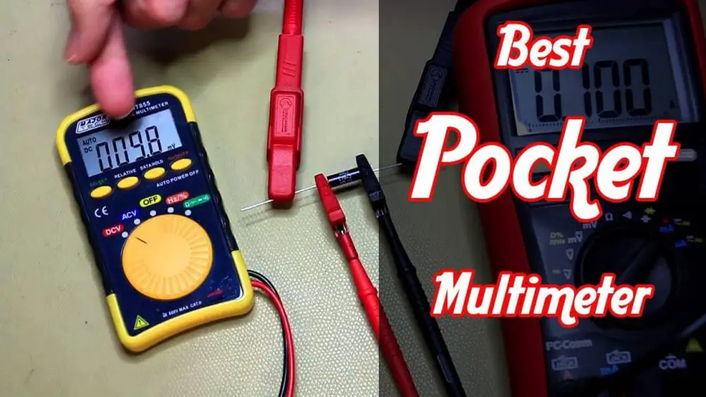
You may find different types of multimeters such as the best handheld multimeter for household use and DIY things. The basic parts of a multimeter include the following:
- The display of the multimeter is the screen that shows the digital, usually four in analog or digital format.
- The selection knob of the multimeter is used to change the measurements for different things, including the resistance, voltage, or current.
- Probes attached to the multimeter are two. One is the COM, which is connected to the ground or the circuit. The other is the mAVΩ enables the users to gauge the voltage, current, and resistance.
Types of the probe in multimeter
There are many probes in multimeters. The detail of a few are given below:
- Banana to IC Hook helps in probing smaller I.C.s.
- Banana to Tweezers is highly useful in testing SMD parts and components.
- Banana to Test Probes is used as the replacement if you have accidentally broken a probe.
- Banana to Alligator Clips used to connect large pins and wires to the breadboard. It helps in holding the probes while you are testing a circuit.
How to use a digital multimeter

Believe me, a multimeter is as important for electrical engineers as a stethoscope for doctors. However, it is imperative to learn the art of using it in the right way. The use of a digital multimeter is pretty easy as given below:
While using the digital multimeter (DMM), it is imperative to understand the primary controls. You can use the switch to control various amps, ohms, volts, and other types. Let’s consider the simple steps to use a DMM:
Are you ready?
- First of all, turn the multimeter on
- Now, attach the probes into the ports carefully as you need to it according to the requirements.
- Adjust the switch properly for taking measurements. For instance, if you are choosing the range, you should consider the max-range for estimations. However, you can change the range of digital multimedia.
- Remember! It would help if you optimized the multimeter range for getting the best results. The accuracy of DMM reading depends on setting an optimized reading.
- Once you have done taking the readings, it is best to put probes into the sockets for voltage checking. Now, put the range to the maximum. In this way, you can eliminate the risks of accidents if the meter is unconsciously attached to a high voltage point.
How to use an Analog multimeter
All multimeters, no matter digital or analog, work in the same ways. It is essential to understand the difference in use because the analog multimeter setting differs from the DMM. With some knowledge nuggets, you can operate the analog multimeters to gauge voltage, continuity, resistance, etc.
Generally, testing using an analog meter is easy, but you have to see a display in the analog format. Usually, it has only one switch for many operations. However, the major difference between the analog and digital multimeter is the position of the probes.
Are you ready to test voltage, resistance, and other measurements using the difference between AC and DC setups on the analog multimeters? Let’s see the steps together!
- Start with turning the analog multimeter on
- Then, plug in the probes into their respective connections. It is one of the most important tasks because any act of negligence can simply ruin everything. So, be careful!
- Now, it’s time to adjust the switch to the right type of measurements. For this, you need to set the range appropriately. Don’t forget to initially set the range at low points to get the correct reading of voltage and other measurements.
- Optimization of range during testing is an essential task which helps you in getting the reading correctly.
- Be careful while recording the reading as it has an impact on your overall measurements. Once you have completed the reading activity, set the analog multimeter for maximum range on voltage to eliminate the risks of accidents.
Yaay! See, it was all easy as a piece of cake. Do you agree?
A basic guide for taking measurements using a multimeter
Nevertheless, it might be dangerous to work with electricity and electronics devices without certain expertise. Therefore, certain learning is essential to manipulate multimeter like a pro. Let’s consider the given below detail to use analog or digital multimeter for different measures without any difficulty:
How to measure DC voltage with a multimeter
To begin with, it is easy to gauge voltage using a multimeter.
- Firstly, you need to plug the probe (red) in the mAVΩ and (black) into the COM port.
- Now, you can adjust the device to 2V in the range of direct current (D.C.). It is imperative to understand that most portable tools such as multimeter use D.C. not alternative current or A.C.
- It is the time to connect the probes: red into the “+” or power while black into the “-.” It will help if you put a little pressure on the probes against the terminals, both the positive and the negative of the battery. If your battery is new, the multimeter will show 1.5V or higher.
Consider the overload
Sometimes, the multimeter shows overloaded values. It happens when the voltage is extremely low that you are measuring. In such a situation, the meter shows only one digit, one. It indicates that the voltage is out of range. So, you can resolve the issue by changing the knob of the multimeter.
How to measure resistance with a multimeter
The simple way to get familiar with the resistance is to understand the colour codes. If you find it confusing, don’t worry, as you may find many calculators online for comprehending the resistance. It will help you measure resistance using a multimeter.
- You just need to adjust the setting 20kΩ on the multimeter and select a random resistor.
- Now, hold the probes to the legs of the resister to measure resistance using a multimeter. It will show any value, either 1, 0.00, or the actual value of the resister.
- Now, it’s time to read the resistance with a multimeter! In a case that you read 0.97, it means that the value of resister is about 1kΩ as it shows 970Ω.
If the multimeter shows O.L. or 1 on the display screen, the value is higher than 200kΩ, and it is overloaded. It is imperative to understand that 5% tolerance is a normal thing in the resistors. It means that 10kΩ can be 10.5kΩ or 9.5kΩ, depending on the discrepancies. Remember! Temperature can impact resistance outcomes.
Multimeter resistance measurement principle
The principles for measuring resistance using either digital or analog multimeters are the same. It is because the same rule is applied to the devices. The fundamental concept is that the multimeter ads a voltage to the probes, and it will help in the flow of current within the device intended to be tested. In this way, you can estimate the resistance among the probes or the tested device.
How to use a multimeter to test voltage or current
It is one of the most critical tasks as you must have the know-how of electronics. It is a bit tricky as you have to gauge current in a series. Before you start with it, you must consider that measuring voltage is different from measuring the current.
In that process, you need to poke the probes parallel at GND and VCC to estimate the current. In this way, you need to interrupt the current while adjusting the multimeter between the circuits. For this purpose, you need a piece of cable that is extra for interrupting the current.
Now, use the power pin for probing. It will break the power circuit, letting you know the current. You can see the current flow in the display.
- You can use alligator clips to measure the current as it comes in handy and let you free your hands from doing other chores.
- It is imperative to understand that you can connect the multimeter to the circuit and then set up the dial for measuring current in the electrical wires.
- You may set the multimeter at 200mA after attaching the red probe to the port. It works the same as measuring voltage or resistance.
However, if you doubt that the circuit is using a closed switch, it is better to set the probe to 10A for safety purposes. In case of overloading, you may end up with a blown fuse. It is because the multimeter is operating like a wire in the system.
It works as the times pass on the microcontroller, the LED, sensor, or any other device may change the power consumption. So, you can see instantaneous readings on the multimeter display. Under the normal condition of 5V, it will show 7 to 8mA, and it will not be 7.48mA.
Remember! Changing the probe doesn’t impact the readings, but it only shows it in negative. For accuracy of results, you can also use the best fluke multimeter for electronics as it will help you ease testing cables and wires to ensure proper current is flowing for higher efficiency.
How to use a multimeter to test continuity
Testing continuity is something important when it comes to checking resistance among two-point. It is because low resistance creates a tone in the points connected electrically. On the other hand, if there is sufficient resistance between the points, the circuit is wide open, and there is no tone. It is significantly helpful in checking that the connections are established successfully.
You may not believe it, but continuity is indeed the most significant function for electrical experts. You can set the multimeter to continuity mode and check the electrical connection breakage. The way of setting is easy as you just look at the diode symbol on display.
Post Note! Not every multimeter has a setting for continuity testing. However, if a breadboard doesn’t have the power, you should poke the probes for hearing the emitting tone for continuity. Don’t forget to turn off the system before checking continuity. Consider the steps below:
- Firstly, check the GND and VCC in case the system is on. You need to check the regular for 4.2V while the 5V system is running. If it is hot, the system has too much current.
- Secondly, if the power system is off, you need to test continuity among GND and VCC. If a beep is emitted, then somewhere the system is short. Be careful.
- Thirdly, check the GND and VCC are connected in the right way while testing continuity. Keep the system power shut for a while and adjust the pins on the microcontroller and other devices. If you see the system is powered up, then I.C.s are cabled in a wrong way.
- Fourthly, you can use a logic analyzer or a serial debugger to check digital signals when the microcontroller is running. In normal testing and troubleshooting, you need to set continuity probing between the VCC rail and the ground.
Easy-peasy tips for changing multimeter fuse
Many newbies use the multimeter to estimate current using VCC to GND probe. It generally ends up in short, and the power supply gets down. It is imperative to understand that when the current passes through the multimeter, the internal fuse burned out by heating up to 200mA. You surely know that it happens in a fraction of seconds without any physical sign and audible symptom.
So, it has been done, and now what’s next? Let’s consider the ways to change a fuse for the perfect working of the multimeter.
- You need to have a handy screwdriver for taking out the screws. Once you have done this, you will see the battery plate and remove it to access the battery.
- Now, lift the device, I mean multimeter, and see the edge with hooks at the bottom. Now, you can slide the multimeter sideways to disengage it from the hooks.
- Once done, you can easily see everything inside the multimeter. Now find the 200mA fuse and replace it gently. You have to do it carefully and then adjust everything back as usual. Look, it was easy!
Characteristics that make a multimeter good!
Last but not least, you might be thinking of how to judge if a multimeter is suitable according to your requirements! Getting a good multimeter is essential for smooth working. So, you should check for certain traits or features.
You may find various types of multimeters having different features. However, the basic functions are the same in every multimedia. Keeping this into consideration, a list of essential features is given below for your help:
- Every multimeter has a display, but good multimeters have a back-lit LCD to take measurements in the dark. In this way, you can check the screen even in the dark.
- The good multimeters offer easy to click settings for different types of measures. You can check the selectors using a soft knob attached to the multimeters.
- Top-quality probes are the essential plus of the good multimeters. Although you can get the probes separately, who denies getting it along with the device!
- An added value of the multimeter is the auto-off as many multimeters have this feature making it good.
Coming up to the end, you know everything about multimeters, including what, why, where, and how. So, what are you waiting for? Purchase the best budget multimeter now and start working!
Related Posts:
How to test capacitor with the multimeter in circuit


