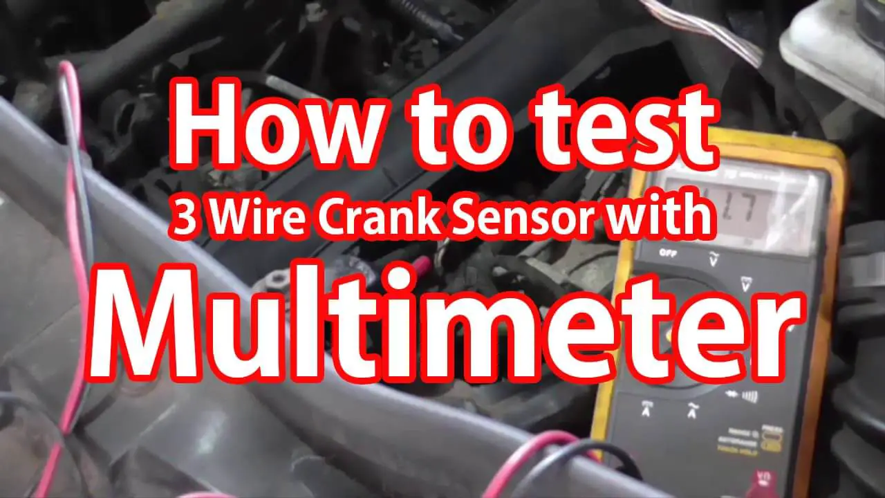
How To Test 3 Wire Crank Sensor with Multimeter
The three-wire crankshaft position sensor is supposed to have about 2000 to 2500 ohms of resistance. So we will choose 20,000 ohms on the selector dial with the help of a multimeter and will take our measurement.
The crankshaft position sensor evaluates the rotation speed (RPMs) and the exact position of the engine crankshaft. It controls the situation and the rotational speed of the crankshaft and sends the notice to the engine control unit to make proper modifications based on running conditions.
Without a crankshaft position sensor, the engine would not start. In some cars, the sensor is placed close to the main pulley (harmonious balancer), the transmission bell housing, or inside the engine cylinder block.
Problems with the crankshaft position sensor can have several issues. 2 common causes include:

- The Overheating Engine: The overheating in the engine can lead to crankshaft sensor damage by melting the plastic covering.
- The Circuitry Problems: A dropped voltage, loose or damaged wiring can disrupt the signals sent to and from the crankshaft sensor, causing problems.
You cannot drive with a failing crankshaft position sensor. It can be difficult and quite dangerous. That can lead to vehicle damage and costly repairs, or even the car will not be working at all.
Table of Contents
Symptoms of Crankshaft position sensor failure
Problems in Starting the Vehicle:
The most common symptom linked with a bad or failing crankshaft position sensor is difficulty in starting. The crankshaft position sensor controls the position and speed of the crankshaft and other vital parameters when starting the engine. If the crankshaft position sensor has a problem, then the vehicle may have intermittent starting issues or not start.
Intermittent Stalling:
Another common symptom is related to a faulty crankshaft position sensor. When the problem is with the crankshaft position sensor or any damage in its wiring, it could cause the crankshaft signal to break while running the engine; it can also cause a stalled engine; this is generally a sign of a problem with the wiring. Similarly, a bad crankshaft position sensor can also produce this symptom.
Check Engine Light Comes On:
Another issue with the crankshaft position sensor could be the illuminated Check Engine Light. If the multimeter detects a problem with the crankshaft position sensor’s signal, it would activate the Engine Light to alert the driver, ensuring the problem. A wide variety of other issues can also set off a Check Engine Light.
Uneven Acceleration:
If the input coming from the crankshaft sensor is inaccurate, the engine control unit could not adjust to spark timing and fuel injection as the engine speed increases. As a result, a slow or odd acceleration would result from inaccuracy and make it difficult to maintain a constant speed.
Engine Misfires or Vibrates:
Whenever you hear or feel a slight stutter in the engine, it may signify misfiring cylinders from a bad crankshaft position sensor. A weak crankshaft position sensor cannot provide the correct information about piston positioning in the engine, causing a cylinder to misfire. Misfire could also occur from faulty spark plug timing, but the crankshaft sensor is the source of the spark plug checks out.
Rough Idle and Vibrating Engine:
This is a problem with a crankshaft position sensor, that is rough idling. For example, while idling at a red light, or it might stop, you may notice the engine or vibrating or grinding sound. Whenever this happens, the sensor is not monitoring the crankshaft’s position; it can lead to vibrations that affect the engine power. In addition, the shaking could interfere with the engine’s tracking of mileage—any out-of-the-ordinary vibrations could be managed by a mechanic as soon as possible.
Reduced Gas Mileage:
when the crankshaft sensor fails and lacks accurate timing information, the fuel injectors would not efficiently pump gas into the engine. The engine uses more gas than it usually needs on a short or a long drive, reducing the overall fuel economy.
How to test the crankshaft position sensor
Whenever there is a doubt that a crankshaft position sensor might cause the problem or a related trouble code, must visually inspect the sensor for cracks, loose or corroded connector pins or other apparent damage. The exact gap between the tip of the sensor and the reluctor ring is also significant.
If the sensor is pick-up a coil type, the testing procedure includes checking the resistance with a multimeter. The resistance we have here, crankshaft position sensor from the vehicle, Ford Escape 2008 model; measures 285.6 ohms, is specific.
For example, for the Ford Escape, 2008 model, the resistance of the crankshaft position sensor (CKP) should be between 250-1,000 ohms, according to Autozone. We measured 285.6 ohms which is within the specifications. If the resistance of the sensor is lower or higher than 285.6, you must replace the sensor.
In addition for the Hall-type sensors, we must test the reference voltage (usually +5V) and the ground signal. The most significant way to test a crankshaft position sensor is by Oscilloscope.
Sometimes, the Crankshaft sensor has an intermittent fault that is not present while testing. Therefore, checking for Technical Service Bulletins (TSBs) and checking for common problems may help.
The signal from the crankshaft position sensor is represented as “Engine RPM” in an OBD II scan tool. You may check the crankshaft position sensor with a scan tool. It determines the sensor signal as “Engine RPM” or “Engine speed.” When do we do that? When a car stalls intermittently, observing the sensor signal would provide you with the answer. If the sensor signals drop down to zero and it comes back again, it suggests an internal problem within the sensor’s wiring.
How to test 3 wire crankshaft sensor with a multimeter
There are a few types of Crankshaft sensors. The first one will be the magnetic type sensor, now these sensors will almost always have only two wires going to them, and these sensors produce their voltage. And the way these sensors produce their voltage, the teeth on your gear will stimulate the magnetic field at the end of these sensors. So then, your sensor will make an AC voltage that’s sent to your electronic control module through this wiring harness connector. So now I will do these testing procedures right here on this bench, but you don’t have to remove your sensor; you can do this on the car.
STEP 1:
First thing first, you want to closely take a look at the plastic housing of your sensor. If you see any significant cracks or signs of damage or bent out of shape, that could mean you have a bad sensor.
We will do a resistance test, so get your best multimeter, and put the selector dial on the ohms settings. Our three-wire crankshaft position sensor is supposed to have about 2000 to 2500 ohms of resistance. So I will choose 20,000 ohms on the scale of this multimeter, and then we will take our measurement.
And as you can see, we got 2.01 thousand ohms of resistance or in other words, 2010 ohms. So also, it is vital to check the condition of the connectors for your sensor. Sometimes oil and dirt and mud get on this sensor and cause all sorts of problems. But if it looks clean or if you clean it, it’s a good idea to check and make sure that you have ground at this sensor. So what you want to do next is to ground your black test lead, and it doesn’t have to be to your battery.
STEP 2:
You can just ground it to your engine or chassis. We go over to our multimeter, and we will choose this setting for continuity which we will also hear a beep if we do have continuity. With our other test lead, we will test our ground wire, and if we hear a beep, that means we got ground, and we are good there. The last and most important of all is to test whether this sensor can put out voltage.
Again these sensors put out AC voltage, so you want to get your multimeter and put it on AC volts, and we will go with 2 volts since most of these sensors only put out about 0.2 to almost 2 volts. Now a scope would be a much better tool to measure the voltage coming out of these sensors, but I am going to assume since most people don’t have one of those. So we are using this multimeter, and if you are doing this on the car. As the engine cranks you know you may not get, you may not see the voltage go up and down as it is supposed to because your multimeter may not be able to keep up.
But you may just see one solid reading. So let us say 0.15 volts by this sensor, but that usually means that you got an excellent sensor or, in other words, a sensor that can put out voltage.
And if you are bench testing this, as you move this gear past this sensor, you will see the sensor produce a very tiny amount of AC voltage; for some reason, this works better. The three-wire sensors, now unlike the previous sensor, don’t produce their voltage. They require 12 volts to operate, so basically, they receive 12 DC volts from your ECU and then based on the position of the teeth on your gear, they adjust to that voltage and then send that voltage as a form of, you know, a signal voltage back to your ECU they have a grounding wire as well.
STEP 3:
When the ignition is ON or in the Cranking position, you always have a constant supply of 12 volts to these sensors; you always have a continuous ground. And if you want to test these sensors, you want to make sure your ground is your black test lead, and then you want to put the setting on your multimeter to DC volts. So our constant supply is 12 volts. Other times it is 5 volts depending on your car make and model, but all of those will be less than 20 volts, so we will go with 20 volts in this setting.
Remove the wiring harness for your connector and then test each pin and the one that gives your voltage. You know that your constant wire, so here in our case, is this third and last one which is giving us 12.2 volts, so we are going to write this one down. This red one is our constant wire. So next, we are going to find our ground wire from the two remaining wires, so while our black test lead is still grounded, we put our settings on our multimeter back to ohms, and then we test the two remaining pins.
STEP 4:
The one where we got next to no resistance we put down as our ground wire, and therefore right now, we have verified that we are getting voltage and we have a stable ground, and the remaining wire has to be our signal wire. So now, how can you test these? get your multimeter, put your setting to 20 DC Volts, and then you’ll need to back probe your ground and signal wire and then connect these to your test leads by alligator clips, and if you want to have an easy job of doing that make sure you use some paper clips to back probe. Again, with the engine cranking or running, you’ll see the voltage that’s coming out of your signal wire, and again you are not going to see it go up and down like it’s supposed to, but you know it will verify that your sensor is putting out voltage.
Frequently Asked Questions:
The usual common symptom associated with a bad or failing crankshaft position sensor is trouble starting the vehicle. If the crankshaft position sensor is having difficulty, the vehicle may have intermittent starting issues or may not start at all.
Symptoms of a bad crankshaft sensor
1. Engine Light is Blinking.
2. It is challenging to start the vehicle.
3. The vehicle is stalling or backfiring.
4. The Engine is Vibrating
Conclusion:
We have explained in detail the different types of Crankshaft sensors. Various symptoms to find out the sensors are broken. We have tested the crank sensors in different car models. The detailed procedure to check the two-wire and three-wire crankshaft position sensor.
Related posts:
How do we know THE OUTLET is 110 Volts or 220 Volts?


