How to test a relay with a multimeter
A relay is an electronic device that controls a system (that’s why it’s called an input loop) or a controlled system (hence called an output loop). The function is to control an automatic circuit. Therefore, an automatic regulator uses a smaller current to control a larger current. So, it functions as automatic adjustment, safety protection, and circuit converter. A relay has fast response speed, steady work, long service life, and small size. To assure these arrangements can play better, the test and maintenance of the relay are necessary. This article will explain the principal relay test parameters, how to test a relay with a multimeter? And an example to test an automotive relay. A relay is working for the rated working voltage, rated operating current, coil resistance, contact load, etc.
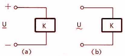
- Rated working voltage follows the voltage required by the coil when the relay is in working position. For example, A/C relays refer to A/C voltage (Figure a), and D/C relays refer to D/C voltage (Figure b). Relays of the same types often have multiple assessed operating voltages for the circuitry needs, and the specification number is added to the end of the component to represent.
Figure 1. Relay Symbol
- The rated working current belongs to the current required by the coil when the relay is usually working. Coil resistance is directed to the D/C resistance of the coil relay. Therefore, ensure that rated working voltage meets the current conditions when selecting a relay.
Figure 2. Rated Working Current
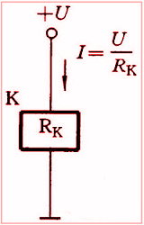
Table of Contents
Types of relays:
First of all, identify the relay you would like to test; there are three types of relays.
The first type is an example of a starter relay for a bike, 2nd type of relay is a five pin relay and it is used in cars, also called a starter relay, 3rd type of relay is issued in electronic circuits, we will learn each and every type;
Type 1: 4 Terminal relay is used in two-wheelers.
Type 2: 5 Terminal relay used in cars.
Type 3: 5 Terminal relay used in electronic applications.
The most common faults usually found in starter relay:
i) Coil: (burnt coil, or broken connection)
ii) Movable contact: (conditions of the relay when lost its movability due to carbon covered/rusty contact or due to sparks)
Common Faults of Automotive Relays
Including, short circuit, coil burnt insulation part ageing, and contact ablation, etc.
1) Relay Malfunction
When the controlled circuit is closed, the relay will not act. On the contrary, the relay will work when the controlled circuit is not required to be completed. The situation occurs because the interference voltage in the circuit overextends the normal range of the drive circuit of the relay. Therefore, consider all the factors that can cause interference (such as grid instability, chip command errors, short circuits, etc.) when making a circuit.
2) Relay Burned
There are many reasons for burnout. For example, the actual switching current exceeds the acceptable switching current of the relay, and the actual inrush current exceeds the rated switching current of the relay. According to design experience, to avoid these problems, you should select the rated current 2-3 times the actual switching current, and the impact current of the relay is 2-3 times the actual current.
3) Contact Welding
When the temperature of the A/C conversion relay coil is higher than the D/C conversion relay because of the magnetic circuit’s current loss and hysteresis loss. In addition, when the relay operates an A/C conversion at a voltage lower than the rated voltage, a bounce phenomenon might occur. It will burn out, all the connections, to the relay will be damaged or disconnect the self-protection circuit. Therefore, you should prevent problems with the power supply voltage.
In addition, the prolonged fluctuation time will cause the failure of the relay. So, make sure that there is a power supply with adequate capacity.
4) Coil Temperature Rise is Too High
If the magnetic materials are lost, such as copper wires and iron cores or the contacts’ heat transfer will cause raising the temperature. Therefore, you should correct the resistance for the insulating materials and measure the distance between the relay and the heat-generating device to make sure the circuitry is working fine.
How to test a relay with a multimeter in continuity?
We can set our multimeter to (buzzer mode/ continuity mode)
For Type 1 and Type 3 relay
The method to test a relay is by using a multimeter.
Set the multimeter selector to the Continuity mode
Step1: Connect the two leads of the multimeter to the coil terminals( C1 & C2)
if the buzzer ring, then the Electromagnetic coil is alright.
If the Buzzer does not give a sound, this means that the coil is faulty.
Step2: If the buzzer rings, it requires checking the output terminals of the relay.
Connect your multimeter leads to the terminals of the relay; if the Buzzer does not ring, this means that the contact terminal is alright. Otherwise, it isn’t very accurate.
OR
Connect your multimeter leads to the terminals; if the Buzzer beeps, this means that the contact terminal is working. Otherwise, it is not working.
Read more: How to test a car fuse with a multimeter
Type 2 Relay test
Continuity mode
Step1: The two leads of the multimeter and the coil terminals 85-(C1) & 86-(C2) are connected to the multimeter; if the buzzer rings, your exciter coil is working.
Step 2: If the Buzzer rings, you have to check the output or Contact Terminals of the relay.
Connect your digital multimeter leads to the terminal (NO terminals) (87 & 30); if the Buzzer does not ring, this means that the contact terminal is working fine. Otherwise, it is not working.
or
Connect the multimeter leads to the (NC terminals) (87a & 30); if the Buzzer beeps, it means relay movable contact is acceptable, otherwise it is broken.
How to test a relay with a multimeter in resistance?
(resistance mode)
(common for all types)
Firstly, Set the multimeter selector dial to Resistance mode. Then connect the Red and Black leads of the multimeter to the coil of the relay.
- The resistance value for the type 1 relay should be between 30Ω to 150Ω.
- The resistance value for the type 2 relay should be between 300Ω to 900Ω.
- The resistance value for the type 3 relay should be between 20Ω to 450Ω.
As shown in the figure, along with it, NO and COM contacts must show 0 Ω, which means it is open-circuited when no input is given.
Read more: How to test a car fuse with a multimeter
How to test relay using a multi-meter in diode-test?
If the relay is impaired, put it in a diode test by taking a multimeter and checking across A1(+) and A2(-). The meter will apply a small voltage to make the semiconductor, and it will conduct and read that voltage on the screen that will check the (typically NPN) transistor from the base(P) to the emitter.
If it does not work the meter will show a reading of 0. or OL, but if the relay is in good working condition, it will read 0.7 for a silicon transistor (almost all of them) or 0.5 for a germanium transistor.
The symbol of an electrical relay is shown in the figure:
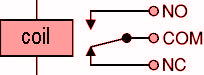
When the current flows through the electromagnetic coil, it acts as a temporary magnet. As a result, it attracts the movable ring, which changes the arrangement circuit, and this change is utilized to work as required.
Therefore, if we open the current or power of the coil, it closes the circuit, and If we stop the power to the ring coil, the circuit loses its connection with the terminal. Therefore, the circuit is not closed.
Read more: How to test battery with a multimeter
Frequently Asked Questions
The car unexpectedly stalls while operating. One of the most common symptoms is ignition failure; The vehicle’s relay suddenly slows while driving. Car not starting; Another symptom of a bad ignition relay is a no-power condition. Dead battery; Battery dead is another symptom of a no-ignition relay. And a burned relay.
To check a relay, the only tool required is a multimeter. First, you have removed it from the fuse box. Then, set the selector dial of the multimeter to measure D/C voltage, activate the ignition cab switch, first, check if there are 12 volts at the 85 positions in the fuse box, where was the relay plugs in (or the place the relay is located).
Conclusion:
The relay consists of an “electromagnetic switch” for controlling high current devices with a low current circuit. In this article, we describe what a relay is? How many types of relays? What are the main functions and faults of the relay? And how to test a relay with a multimeter.
Recommended posts:
How to test car speaker wire with a multimeter


")
