
How to use a Clamp Meter
The clamp meter is a device used to check current with a clamp of a meter attached superficially to a wire without direct contact with the wind to check direct current(DC) and alternating current(AC).
We will describe to you how to use a current clamp meter; we will use the popular Uni-T UT 202A A/C clamp meter and the Uni-T UT 203 A/C, D/C clamp meter models to demonstrate. First, we learn what a clamp meter is; the clamp meter is a metering device capable of measuring current without direct contact with that current.
This is one of the main advantages of a clamp meter compared to a traditional ammeter and millimetres.
You do not need to break the circuit to conduct measurements. You can conduct measurements of the line under-voltage as well as measuring the high currents operational safety.
This is one more advantage you can measure the current of an insulated conductor.
Function of a Clamp Meter
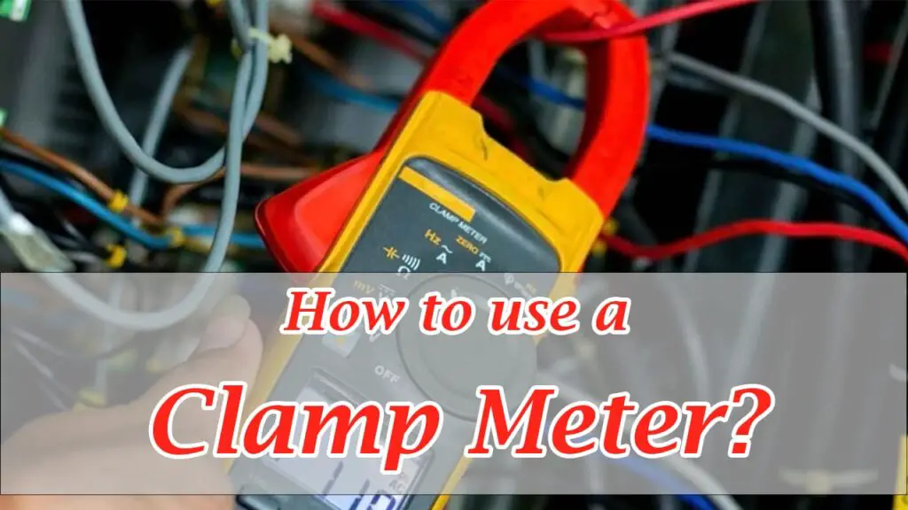
Measuring current with these meters is simple; switch to the required measuring range of current. In this clamp meter, it is 600 amps. Press the trigger to open up the clamp’s jaws, place the conductor inside, and close the clamp.
Table of Contents
How many sensors is in a Clamp Meter
The display then shows the measurement results in the main element of a clamp meter. It has a current sensor; two types of sensors are used; one type is a current transformer, and the other is a hall sensor depending on the sensor used.
Alternating Current and Direct Current
The meter may measure either alternating current or direct current. For an alternating current, we use a clamp meter with a current transformer. In this meter, inside the plastic housing, there is a magnetic core. If you open up the clamp, you can see its parts.
Primary and Secondary Windings measures with a Clamp Meter
The conductor that measures the current acts as the primary winding, and the secondary winding is inside the plastic housing. It has a transformer, so you can only measure alternating currents. The other type of design of clamp meters instead has a Hall sensor; there is no magnet.
If you open up the clamp’s jaws, you can see that the advantage is that the hall sensor can detect both AC and DC.
Let us start with some alternating current(AC) measurements.
Note:
The main thing you need to remember for measuring the current is that you have to clamp exactly the conductor you want to measure.
If we clamp both sides simultaneously or the whole cable, we will get a zero result because the meter only detects the difference between the currents; because both of these conductors carry the same current, the difference will be zero.
If you have a cable consisting of several wires and need to measure each of them, you do not need to strip anything. You need to find a place where the cable is divided into separate wires; for example, start measuring the current somewhere in the electric cabinet.
Note:
The most important thing is remembering when measuring current in a clamp meter to set the reading to the correct measurement range.
Maximum and Minimum range of Clamp Meter
If you are unsure what current range to use, you have to start with the maximum. I will measure the current used to power this electric teakettle; let us assume that I do not know what current is being used, but it has to be lower than 600 amps.
Now turn the kettle on and switch the meter to alternating current with a 600 amps range. Put the clamp on the wire; the kettle uses some current of about 7.00 amps. Now switch this to a lower range of 200 amps; we get 7.6 amps to measure the current with the best accuracy possible, switch it to the 20.0 amp range.
Result:
The meter shows 7.73 amps. If I clamp both wires, I will get something around zero.
You have to follow the rule of only clamping one conductor.
Now take the meter with a Hall sensor. The measurement procedure is very similar.
One difference is that you have to set the readings to zero before starting a new measurement because the hall sensor is magnetically sensitive.
So turn the display reading to zero and then measure; we get a current of slightly less than 8.00 amps.
Three Phase Circuit Test with a Clamp Meter
Now I will use the Uni-T UT 203 clamp meter to measure current under real-time conditions in a 3-phase circuit.
First, we turn the rotary switch to the current measuring position and then switch it to alternating current measurements.
Starting with a phase of 47.00 amps; we can press the hold button to store the result. The second conductor is 278.0 amps, and the third conductor is 46.00 amps and now will demonstrate some direct current measurements.
We have a power supply unit providing 3.00 amps of current in this circuit. First, we will switch the meter to the 40.00 amp range because the hall sensor is very sensitive.
We need to turn the display zero reading.
Now we can measure the conductor. It shows three points one is 5.00 amps, the absolute accuracy is about 150 to 170 milliamp, but that is not much taking into account, that our measuring range is 40.00 amps a current transformer clamp meter cannot measure this current at all.
Like a most modern clamp reader in addition to current, these two models are capable of measuring voltage and resistance, and they have a continuity buzzer. Diode test functions are fully functional millimetres with a non-contact current measurement function.
Frequently Asked Questions
Yes, Uni-T UT 203 Clamp meter can check both A/C and D/C voltage.
Yes, Mostly Clamp meter comes with Bluetooth.
Yes, we can use a clamp meter for automotive use.
Conclusion:
In this article, I have tried my best to describe how to use a clamp meter and a detailed explanation of all of its functions. In this review, the procedure to check direct current(DC), an alternating current(AC), comes up when using a digital clamp meter.
Related Posts:
How To Test Capacitor With The Multimeter In Circuit


